Lab 8: Digital Packet Radio – APRS
Overview
This lab is a condensed version of a final project from a previous quarter. In it, we will capture and decode digital packet radio signals. The specific system we will look at is the Automatic Packet Reporting System, or APRS. This is an amateur radio combination of Twitter and Find My Friends.
The idea behind APRS is that an APRS user can transmit a digital radio packet anywhere in the world, with a payload of 256 bytes. This will be retransmitted by digital repeaters (digipeaters) for a specified number of hops. This allows direct digital radio connections over long distances, such as most of northern California.
Beyond this, internet nodes (i-gates) pick up the packets and forward them to a web site where they can be viewed with a browser (aprs.fi). This provides global coverage. If you want to have some independent device to report from somewhere out in the world, this a a great resource. One common device is a weather station. Another group that uses APRS is high altitude balloons. You can also make a tracker for your bike, so that you can find it when it is stolen!
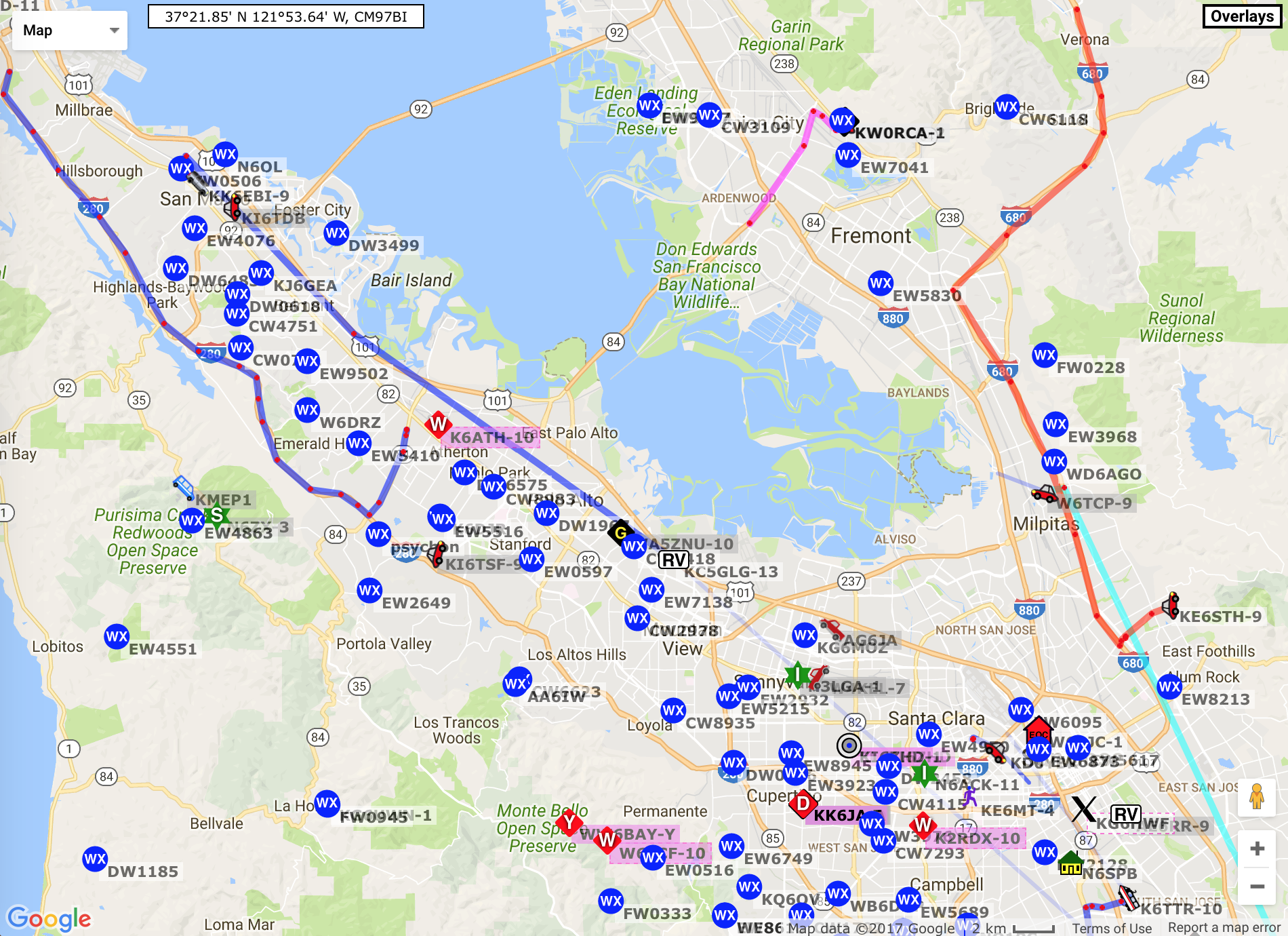
A map of active APRS sites on 5-24-17 in our area looks like this:
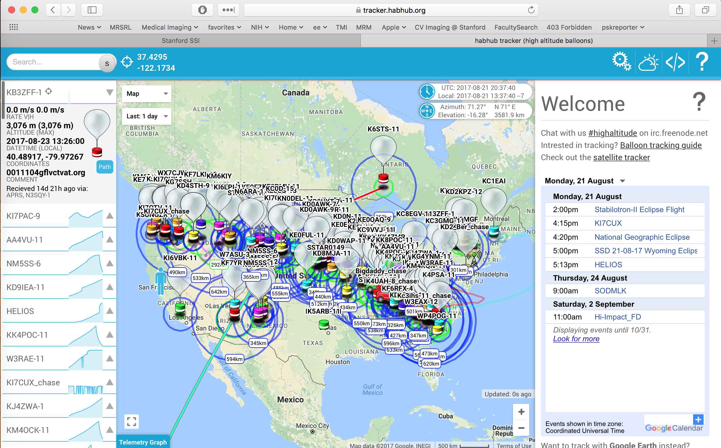
People who fly high altitude balloons also often rely on APRS. The 256 byte payload allows reporting of position, altitude, temperature, battery status, among others. These are all available at the habhub.org web site. The balloons that are up over North America on a typical day are shown here
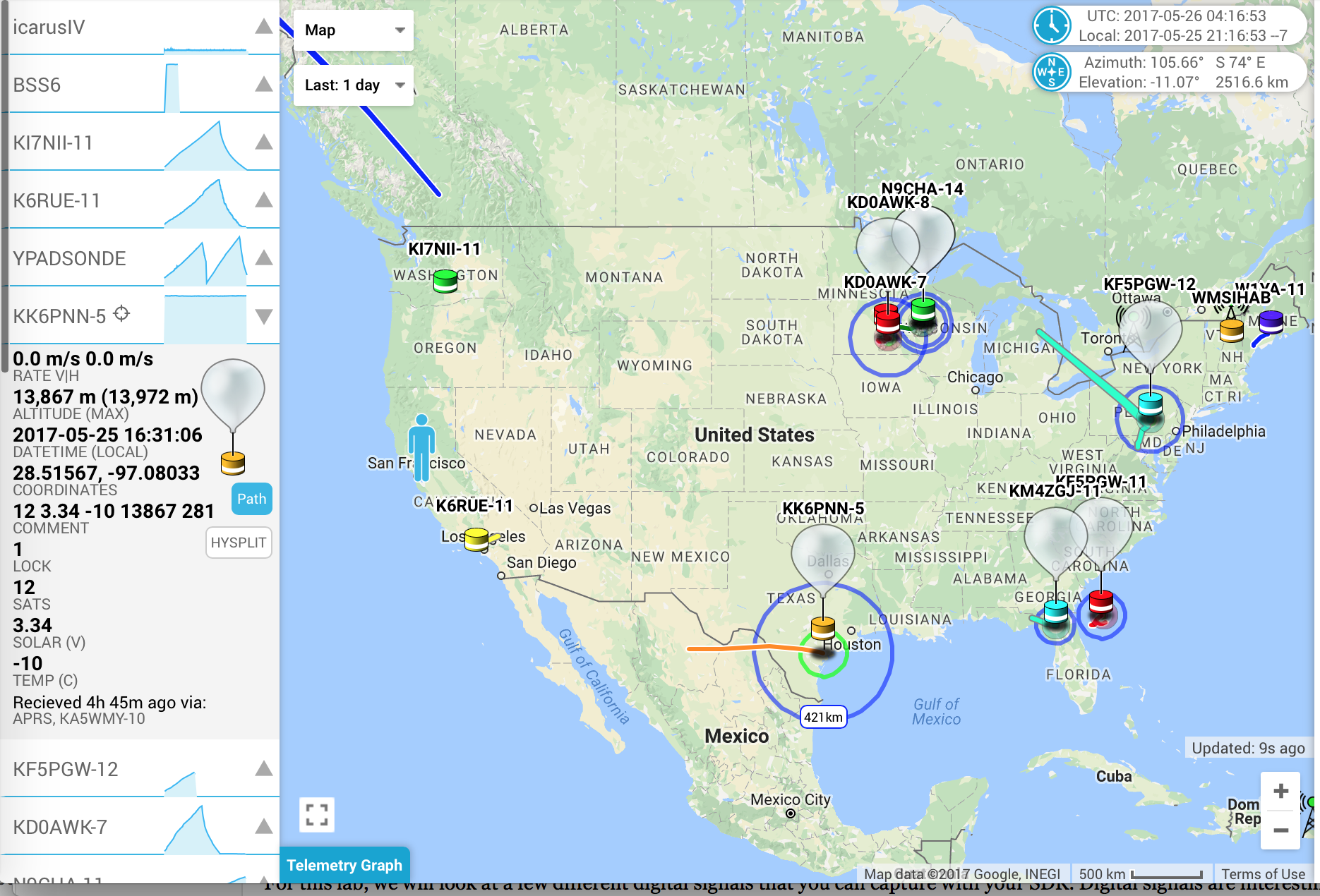
Some days are busier than others. Can you guess what was happening on this day?
If you want make a small device that you can send out into the world, so that you can track it and receive data from it, APRS is a very inexpensive (free) and capable solution. For example, there are arduino shields that do APRS. Anything you do with an ardiuno can be tracked and accessed anywhere in the world.
In this lab we will look at the APRS packet network, and examine how to decode APRS packets.
Structure of APRS
APRS is based on a shared frequency. Packets are all sent asychronously, and can interfere, just as in baseband ethernet. In the U.S. the frequency is 144.39 MHz. With ethernet, collisions are detected, and packets retransmitted. With APRS the receivers are all varying distances from the source. Most packets are picked up by some station, and the overall packet loss is low. Packets are either detected or lost.
Part 1: Transforming APRS RF Signals into Bits
In the first part of the lab, we will look at turning the APRS RF waveform into bits. The APRS packets are transmitted using the Bell 202 1200 bit/second modem protocol. This uses a standard called AFSK1200, for Audio Frequency Shift Keying, 1200 baud. The packet itself is encoding using the AX.25 protocol. This is an RF extension of the X.25 protocol which is an ITU standard, and an alternative to IP. In the first part of the this lab we will detect the bits that are transmitted in a packet.
Part 2: Decoding APRS Packets
In the second part of the lab, we will look at decoding the bit stream from the first part, and turning this into digital ascii data that we can interpret.
Part 1: APRS RF Decoding
APRS uses the Bell 202 standard for sending bits over a bandwidth limited line. At the simplest level, a ’1’ is sent as a tone at 1200 Hz, and a ’0’ as a tone at 2200 Hz. At 1200 bits/second, each bit is 0.83 ms, and a ’1’ goes through 1 cycle over one bit at 1200 Hz, and a ’0’ 1.8 cycles over one bit at 2200 Hz. This is enough to be able to distinguish the bit pattern of the input waveform.
If we use an rtl_sdr, we can acquire APRS data
> rtl_sdr -f 144390000 -n 41920000 -g 30 aprs.dat
This is centered on the APRS frequency, and collects 20 s of data with a receiver gain of 30 dB. However, the devices that produce APRS packets are quite variable, and some packets are much more difficult to decode than others. To get started, use this sample file acquired at 2.048 MHz is
This has two well defined, well separated packets to look at. First load the data, and decimate by a factor of 64 to 32 kHz.
> dd = decimate(decimate(loadFile('aprs23.dat'),8,'fir'),8,'fir');
> dd(1) = 0; 					% suppress transient
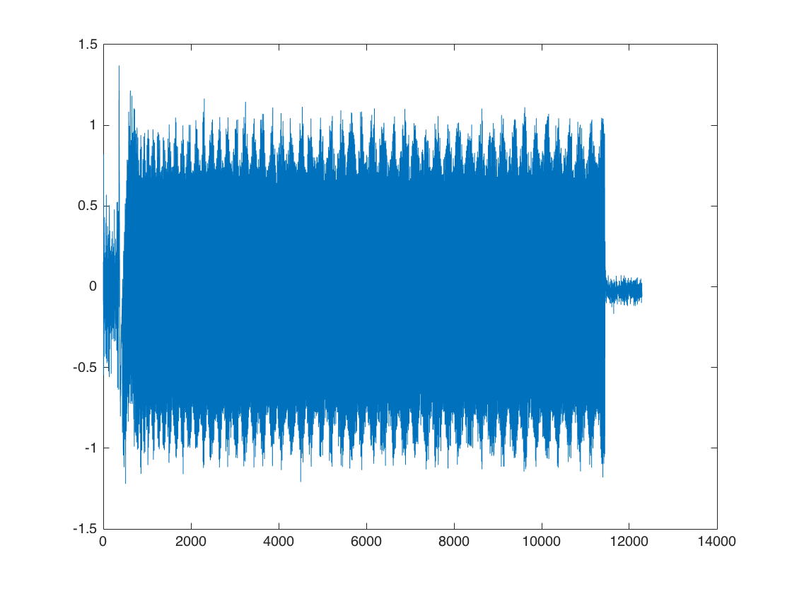
This reduces the sampling rate to 2048000/64 = 32000 Hz. The result looks like
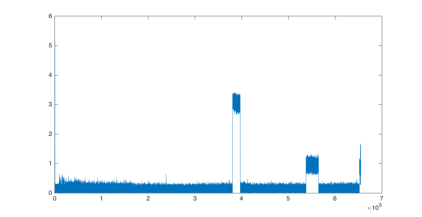
We can extract the first packet with
>> dp = dd(3.8e5+(1:16384));
>> dp = dp - sum(dp)/length(dp);
This extracts the packet, and then subtracts off the DC bias (this was acquired right on the APRS frequency).
Since we ultimately want to sample at 1200 bits/second, we want to resample at some multiple of that rate. We will choose 24000 samples per second, so that each physical sample will be 20 samples of the RF waveform. Since we are already sampled at 32000 samples/second, We then need to downsample by a factor of 3/4.
>> dps = resample(dp,3,4);
At this point, we can use narrowband FM decoding to resolve the input signal into two frequencies
>> dpf = angle(conj(dps(1:end-1)).*dps(2:end));
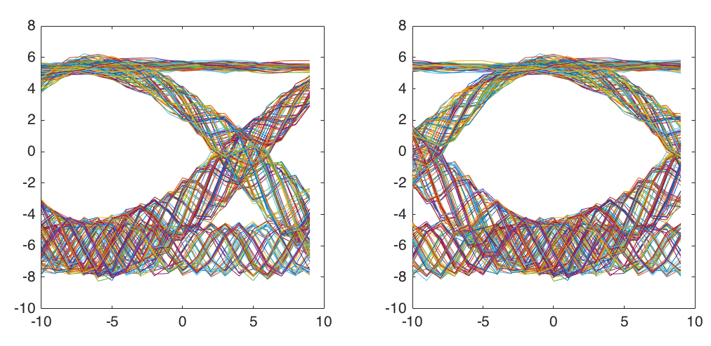
Plotting the result for the whole waveform on the left, and the first part on the right:
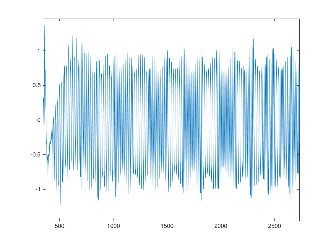
You can easily see the two different frequencies for the two different bits.
Non-Sychronous Detection
An efficient way to do the decoding is to use matched filters for the two different waveforms we are looking for
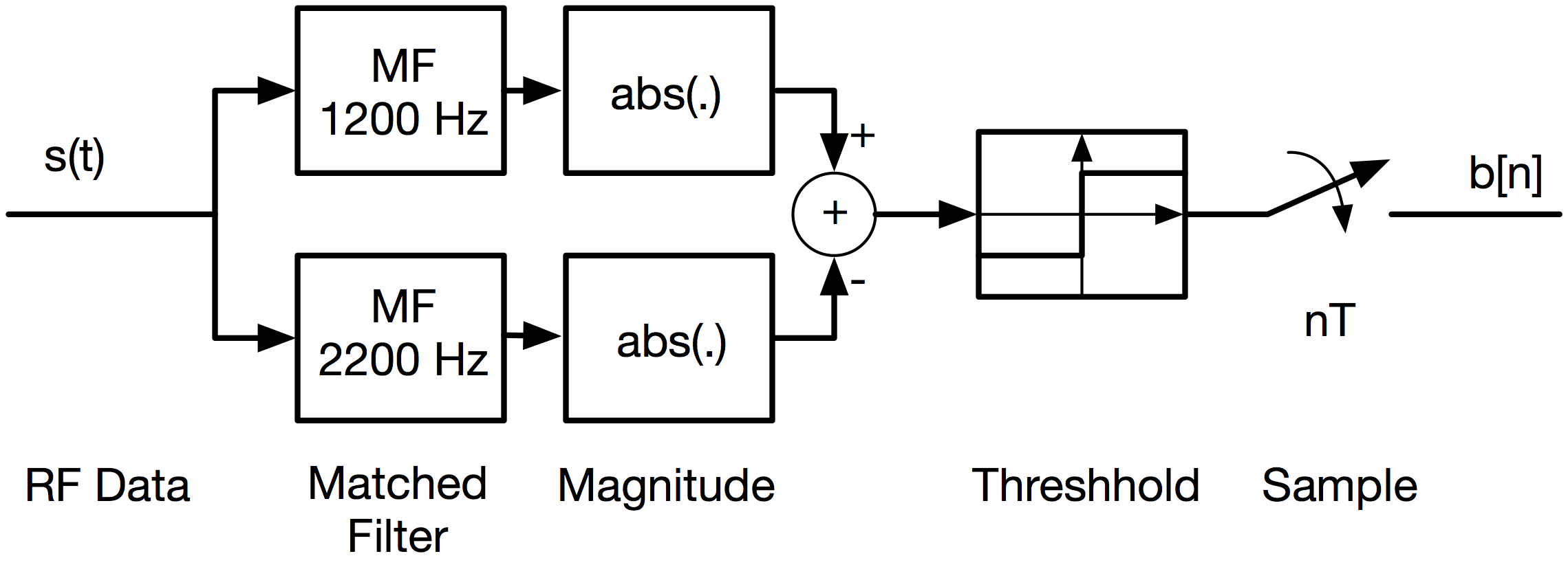
One matched filter is one cycle of a complex exponential over 20 samples (the 1200 Hz Bit) and the other is 1.8 cycles over 20 samples (the 2200 Hz bit).
>> t20 = [-10:9]/20;
>> mf1200 = exp(i*2*pi*t20*1.0);
>> mf2200 = exp(i*2*pi*t20*1.8);
If we convolve the input signal with each of these, and take the absolute value afterwards, we can isolate the two cases. One of the two channels may be sufficient, but combining the two by subtracting improves noise performance.
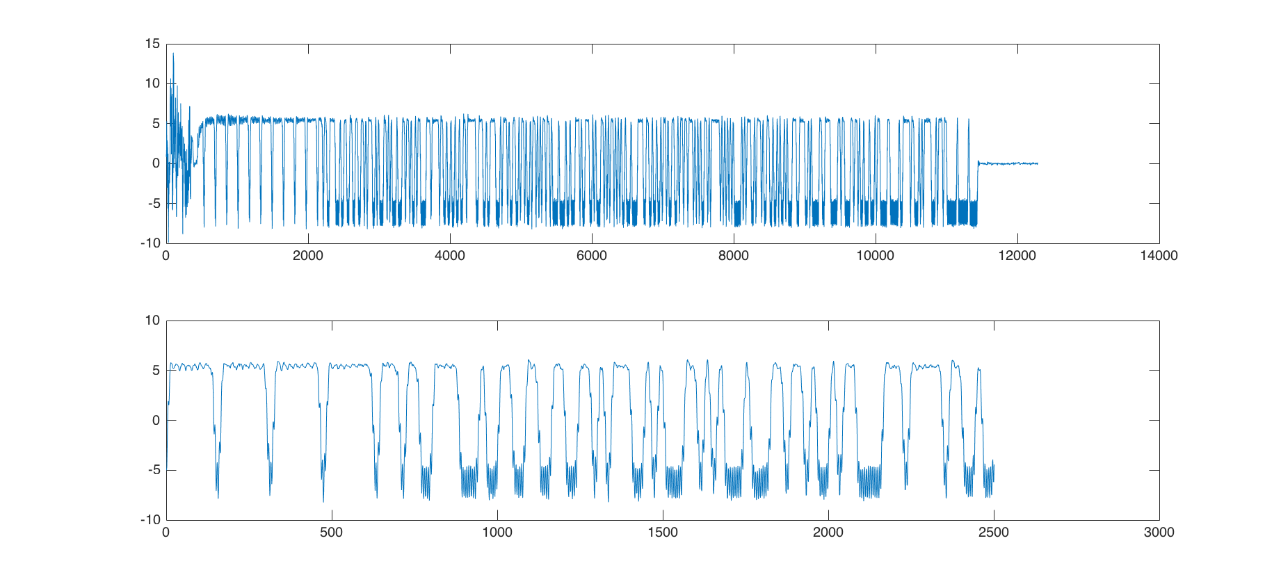
>> d12 = conv(df,mf1200,'same');
>> d22 = conv(df,mf2200,'same');
>> ddif = abs(d12)-abs(d22);
The result is shown below, where the top plot shows the entire packet, and the bottom plot zooms on on the beginning of the packet:
Timing Extraction
A major concern is synchronization with the individual symbols. We want to make sure we sample when we can best discriminate between the two symbols. In practice we want this to be done automatically, but for this lab we'll just do it by hand using the eye diagram.
We choose a starting sample in the framing bytes, and an ending sample somewhere in the packet
>> n1 = 2000;
>> n2 = n1 + 20*256 - 1
Choose n2 to be an integer number of samples into the packet (here 256). We can then make an eye diagram with
>> boff = [-10:9];
>> eyed = reshape(ddif((n1:n2)-10),20,256);
>> plot(boff,eyed);
The -10 shifts the bits to the center of the plot. You will see something like the plot below on the left,
Shifting six samples earlier lines the eye up directly in the middle, shown in the plot above on the right.
>> eyedm6 = reshape(ddif((n1:n2)-10-6),20,256);
>> plot(boff,eyedm6);
This shows that we have a timing tolerance of about +/- 5 samples at a decision level of 0. This also shows that synchronization isn't an issue, or the eye would be blurred, and the opening would close. The sampled bits are then
>> bts = ddif((7:20:end)-6)) > 0;
We've dropped the -10 so that we will sample in the middle of the symbol.
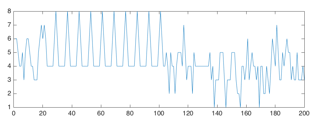
If you plot the first 250 samples, you should see something like this:
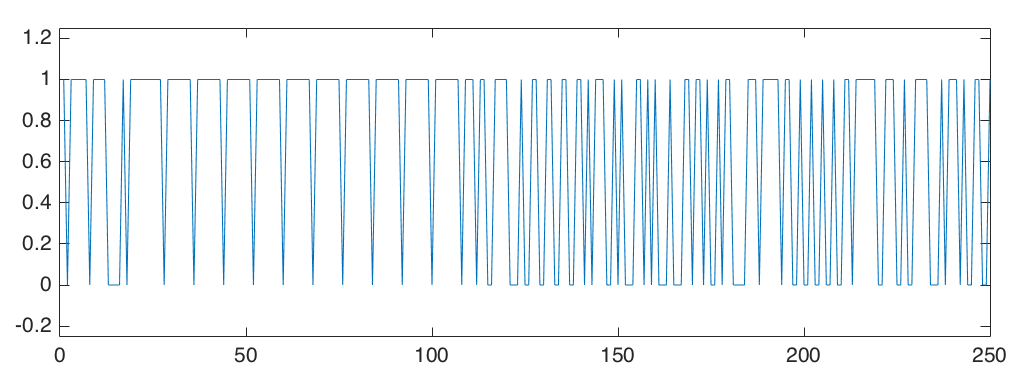
There are some initial bits where the radio is powering up, then a sequence of frame bytes for synchronization, followed by the data bytes.
Part 2: Decoding APRS packets
APRS packets are encoded as a sequence of bits, grouped into 8 bit bytes. Each byte is an ascii character. To decode the stream of bits we have detected in part 1, we have to process them to undo the line encoding used, synchronize with frame bytes, undo bit stuffing, group the bits into bytes, and then find the characters.
In order to skip some of the obscure details of APRS, we will give you an m-file that does the APRS packet decoding
This calls several m-files that implement key elements of the protocol that you will need to write. These are described below.
Line Encoding
The APRS packets use a non-return to zero, inverted (NRZI) line encoding. Output bits are decoded by
If the input bit is the same as the previous input bit, “11” or “00”, the output is 1.
If the input bit is different than the previous bit, “01” or “10”, the output is 0.
Start with an input bit of “0” for one of the timing frames
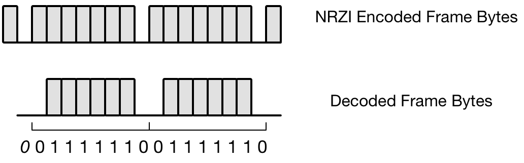
This is best illustrated with the timing frame bytes at the beginning of the packet. The bits before NRZI encoding are “01111110”. The specification says there should be one byte like this at the start and the end of the packet, but usually there are several at the start, and often none at the end. The result of NRZI encoding is shown below, as well as the decoding,
Write an mfile
function [ db ] = decode_NRZI( bts )
%
% Decode an NRZI bits stream bts
%
Then apply it to the bit stream from the first part.
>> db = decode_NRZI(bts);
You should get something that looks like this
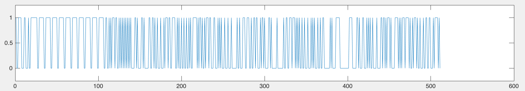
You can clearly see the frame bytes at the beginning. Make sure there are six ones, with zeros on either end (so there are two zeros in a row for adjacent frames).
Synchronization
In the first part we used the eye diagram to synchronize with the individual bits. Here we use the frame bytes to find the beginning of the packet. The frame bytes are [0 1 1 1 1 1 1 0 ] after the NRZI decoding. We can tell if a frame byte starts at a position kk by
>> fb = [0 1 1 1 1 1 1 0]';
>> sum(~xor(db(kk:kk+7), fb)) == 8
If we do this for the first part of the packet, the result is
The packet data starts with the first data byte after the last frame byte.
Write an m-file to synchronize to the frame bytes
function [ dbs ] = frame_byte_sync( db )
%
% Take a packet that has been NRZI decoded, and synchronize to the frame bytes
%    Find the first frame byte
%    Skip over all of the following frame bytes
%    Return the bit stream following the last frame bytes
%
This will find the first frame byte by scanning a bit at a time, and then eliminate subsequent frame bytes a byte at a time. It returns the bit sequence starting at the first bit of the packet.
Bit Stuffing
The APRS packets also limit the number of “1”'s that can be transmitted in sequence to 5 bits. After 5 bits are transmitted, an extra zero is forced into the bit stream. During encoding, this is done before NRZI encoding is done. As a result, we have to throw away those extra zeros at this point.
Bit stuffing is illustrated below. In the original bit sequence we want to transmit there are 8 “1” bits in a row. Since we can only transmit 5 “1” bits in a row, a stuffed “0” is inserted, and all of the subsequent bits delayed by 1 sample.
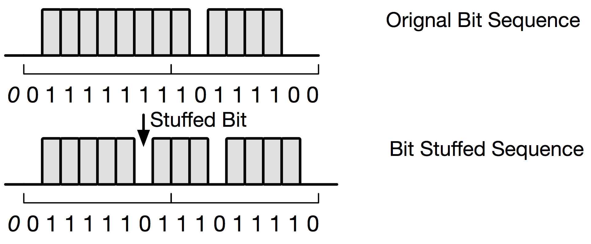
When we receive the bit stream, we need to detect when 5 “1”'s in a row were sent, so we can delete the bit stuffed “0”, and move all the subsequent bits up by one bit.
If we look at the NRZI decoded bit stream from the previous section, and convolve it with five ones
>> plot(conv(dbs,ones(1,5));
We get this
This effectively adds every set of five bits, and outputs a 5 if they are all ones. We see several times where there are 5 bits in a row, where we are going to have to eliminate bit-stuffed zeros. There are two samples that are 6 bits in a row towards the end of the packed (the convolution is 5 for two adjacent samples). These are frame bytes that are sent out to indicate the end of the packet.
Write an mfile to do this
function [ dbsd ] = de_bit_stuff( dbs )
%
% Take a bit stuffed sequence of bits, and eliminate the stuffed zero bits
%
At this point we have decoded the packet bits. We just need to collect them into bytes, and convert them to characters. The bits are transmitted least significant bit first. If 8 bits are in an array b, the byte value, and the ascii character are
bv = b(1)*1 + b(2)*2 + b(3)*4 + b(4)*8 + b(5)*16 + b(6)*32 + b(7)*64 + b(8)*128;
c = char(bv);
Write an mfile that takes your decoded bitstream and returns the ascii string that the packet decodes to,
function [ cs ] = bits_to_char( b )
%
% Take a bit stream and convert it to ascii characters
%
You can tell if you are close when you start seeing call signs (KD7LED for example). Some of the payloads are actually numeric values, that give you funny characters. If you are getting mostly real characters, you are probably doing everything right. Include what you find with your report.
Additional Packets
Another capture with two packets is here
These are longer, and a little more interesting. There is a web site in the first packet, and a location in the second packet.
Lab Report
For your report include
Your m-files for the NRZI decoding, frame synchronization, bit destuffing, and converting bits to characters
A plot of the first 200 bits of your packet after NRZI, synchronization, and bit destuffing,
The decoded packet characters for this packet,
Your decode of one of the packets in aprs22.mat above.